Quick Start
Let's discover SkyWire Studio.
Getting Started
Get started by entering the 'Wiring' application from the navigation button on the top right.
Creating a Project
Before you can save a file, you'll need to create a new Project. To do this, navigate to:
File → New Project
Give your project a name, and click Save.
You'll notice your Project name appears in the top left of the application now:
{ProjectName} / Untitled File
Your first wiring diagram
Page Layout
Title Block
The title block of your diagram will be automatically populated as follows:
- Title: Populated with the file name after saving a file for the first time
- Drawing (DWG): Populated with the specifed drawing number when saving a file for the first time
- Revision (REV): Populated with the revision number
- Sheet: Populated with the currently displayed sheet number
- Drawn: Populated with the initials of your name
- Logo: Populated with SkyWire Studio logo unless a Pro user with a specified logo URL

Drawn By
If you wish to modify the DRAWN field initials, this is based on your name specified in Account → Profile.
Logo
If you wish to add your own logo, this is based on your logo URL specified in Account → Profile.
Sheets
Pro users may add additional tabs to their diagrams for organizing their interconnects. For example, you may wish to only draw serial data connections on one sheet, power/grounds on another sheet, and audio connections on another.
Add a sheet
Select the + icon to add an additional sheet.
Adding LRUs
Pro Users
Generally, most Pro users will begin a new diagram by utilizing the Data Interconnect Wizard or adding an LRU from template.
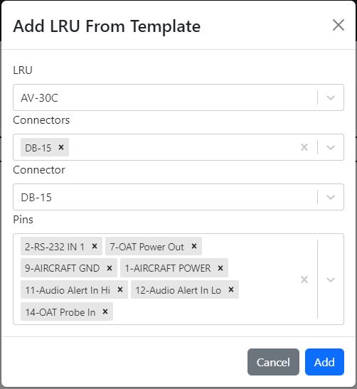
Add LRU From Template
By choosing LRU → Add LRU from template, you can select connectors and pins to add all at once, or just add the LRU without any connectors or pins.
Most of our users find adding all pins the connector, and paring down from there, is the easiest way to get started on a diagram. You can see all of the pins on one page and quickly make the connections.
The fastest way to populate all pins is to add the LRU, then select Connector → Add connector from template or if you already have connectors,
Connector → Add pins from template to existing connector.
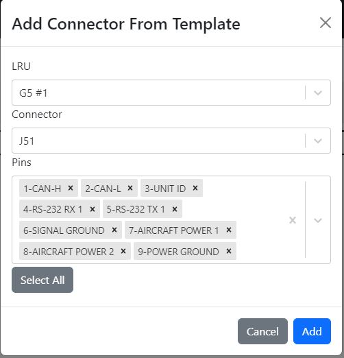
Add Connector from Template
When you select Connector → Add connector from template, you can choose your LRU and the Connector you want to add. A Select All button exists
to add all pins to the connector. This is probably the preferred way to quickly get started.
Add Pins from Template
When you select Connector → Add pins from template, you can choose your LRU and the Connector you want to add. Please note that
the connector must already exist on the LRU or you'll have to use Connector → Add connector from template if the connector does not already exist. A Select All button exists
to add all pins to the connector.
Free Users
Free users are limited to creating custom LRUs via LRU → Add custom LRU.
Using the Wizard Tools
Connecting serial interfaces can be repetitive. Our Pro users enjoy the option of quickly wiring up standard interfaces such as ARINC 429, RS-232, Ethernet, HSDB and others with our wizard tools
Add A Data Interface
After adding LRUs, you can utilize Interfaces → Add a data interface at anytime to quickly assist in connecting serial data interfaces between LRUs.
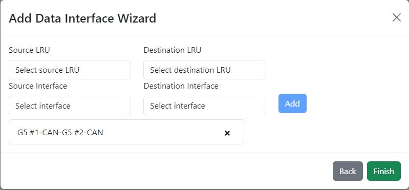
Step One - Select LRUs
In this step, you'll choose the LRUs from the dropdown that you wish to connect together. You must have LRUs already on your diagram to populate teh LRUs dropdown.
Select each LRU and click Add, before proceeding to the next step.
Step Two - Select Source and Destination
Start by selecting the Source LRU for the connection. A list of supported data interfaces will populate in Source Interface dropdown. Select the interface you wish
to connect. Perform the same steps for Destination - note that the Destination Interface will filter to match the selected interface from the Source. If the
two units do not have matching, supported interfaces, the list may be empty. Once done with the individual connection, click Add. This will add the connection to the list of connections to be added by the wizard.
Remove connections from the list by clicking the X icon on the list entry.
Finish
Clicking Finish will populate the LRUs with the necessary connectors, pins and wires.
Data Interconnect Wizard
Utilizing the Data Interconnect Wizard allows you to specify a list of LRUs and their connections to automatically place the LRUs on the sheet and
connect them together based on your specifications. Please note, this method clears any existing work on the current sheet. If you'd prefer
to add serial interfaces to the existing sheet, utilize Interfaces → Add a data interface.
This wizard works exactly the same as Add A Data Interface with the exception of not requiring LRUs to already exist on the sheet.
Using the Data Interconnect Wizard starts your sheet from a clean slate. If you have anything on the sheet, it will clear everything. A confirmation pop-up will be displayed to ensure you want to proceed.
Making Connections / Wires
To get started adding connections after you've added LRUs to the diagram, enable the Quick Connect tool by clicking the double arrow icon button on the toolbar.
Add Connection
With the Quick Connect tool enabled, you'll see red dots that represent the possible connection points.
- Select the starting point, or output pin, by clicking on any of the possible connection points
- Select the ending point, or input pin, by clicking on any of the possible connection points
A connection will be drawn automatically between the two selected points. To disable the Quick Connect tool, click the icon button again.
Canceling
To quickly disable the Quick Connect tool, press the ESC key.
Moving Connections
Connections can be manipulated in several ways.
By Moving Pins
You may click, hold and drag pins around by clicking on the pin number or label. This will cause the connection to follow the pin as you drag.
By Dragging Connection
Connections that are not completely straight horizontal can have their midpoint sections repositioned by:
- Hovering over the connection to highlight it
- Click and hold to drag
- Drag to reposition the mid section of the connection as needed
Dragging Symbols
Symbols can be dragged around the page freely, automatically repositioning the connection.
Modifying Connections / Wires
Labeling
To label a connection/wire, right click the connection and select Label Wire. Enter a label and click Save.
Depending on the length of the connection, two labels may be shown. They will automatically reposition as you move the connection around.
Coloring
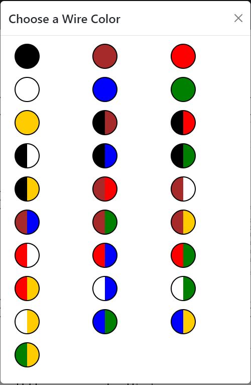
To set the connection color, right click the connection and select Set Color. Select a color from the pallette. We support single and striped colors.
Delete
To delete a connection, right click the connection and select Delete Wire.
Symbology
Symbols can be added from the Symbols menu. The currently supported symbols are:
- Signal Shield Ground
- Airframe Shield Ground
- Airframe Ground
- Antenna
- Audio Jack
- Circuit Breaker
- Annotation
- SPST Switch
- SPDT Switch
- Momentary Switch
- Potentiometer
Adding a Symbol
Select the symbol from the Symbols menu. Some may require configuration before they appear, such as the Circuit Breaker.
Once selected or configured, the symbol will appear at your mouse position. To finalize adding the symbol to the diagram, click once
wherever you want it displayed.
Canceling
To cancel adding a symbol, press the ESC key.
Manipulating Symbols
Symbols can be dragged around the page freely, automatically moving the connections as needed.
You may delete symbols by right clicking the symbol and selecting Delete.
Freeform Text
Text can now be added freely to any diagram using the Text Tool.
Adding Text Labels
To start adding text labels to your diagram, enable the Text Tool by clicking the tool icon. This will toggle the tool on
until you toggle it off. You can also cancel adding text at anytime by pressing ESC on your keyboard.
Once you have the tool enabled, Double Click anywhere on your diagram to create a text box.
Type in your text, and to finish press Enter. To cancel the text, press ESC or disable the Text Tool.
Modifying Text Labels
To change the text, Double Click any text field to enter Edit mode. When finished press Enter. To cancel the edits and
revert the changes, press ESC.
You may also resize the width of the field to force the text to grow vertically. Single click the text to show the transform tool.
Text may also be rotated using the transform tool.